The TXV
Summary
The TXV is a metering device used in the HVAC industry. Its purpose is to meter the refrigerant, or restrict it as much as possible are as much as needed. The TXV is part of the metering device family, to say the least. There are several styles as well as types of metering devices. There also are several types of thermal expansion valves i.e., TXV . It is the fourth component in the refrigeration cycle needed for refrigeration compression to take place. It’s usually not as visible s the other three components. The location is mostly in the evaporator cabinet. And sometimes it can be a fixed orifice tuck between two mechanical nut fittings.
Example image: 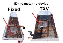 Example image:
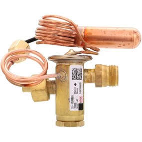
TXV with threaded connections on the inlet and outlet ports, with an external equalizer valve and a sensing bulb. A common valve used in residential HVAC.
Example image: 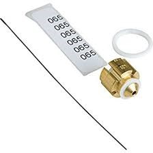
Fixed orifice (piston) is also used in residential HVAC. The TXV meters the refrigerant in the evaporator using spring pressure and the sensing bulb. During this process, it monitors and tries to maintain superheat in the evaporator coil. There are a 20% flash gas and an 80% cold liquid at this stage which is considered to be a dramatic amount of temperature change.
Example image: 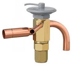
The above image is that of “sweat in” or “braze in” TXV which is common in residential HVAC usually they are located in the outdoor section of a heat pump system. The same principles apply when it is called on to operate as mentioned in the above passage of this course text.
Diagnosis, Troubleshooting, and Installing or replacing a TXV
In diagnosis a TXV the first thing a tech should do is verify the HVAC system has a TXV for a metering device. That can be confirmed by checking the nomenclatures on the front of the evaporator coil panel or electric air handler top panel. If it not legible then the next step would be to remove the panel on the evaporator coil or electric air handler depending on what type of evaporator is at the site. Once the TXV is located or verified then proceed to the thermostat and cycle the system to auto and cool setting on the wall thermostat. Let the system run for 15 minutes then proceed to connect refrigerant manifold gauges to the high side and low side of the outdoor heat pump or straight cool ac system. The high side would be the small pipe connection with the red hose and the low side would be the larger pipe for the blue hose.
Example image: 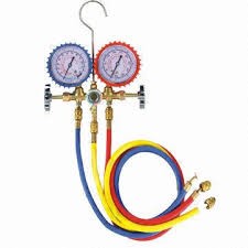
Analog style refrigerant gauges without pipe clamps
P T CHART
Example image: 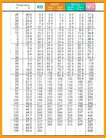
Example image: 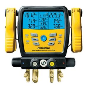
Digital style gauges with pipe clamps
Once the hose has been connected whether it’s with the digital or analog gauges verify the suction pressure and the liquid pressure to determine if they are within the manufactured required levels. one way to determine if there could be a problem with the TXV would be if the suction pressure is reading low or in a vacuum. The second thing to look at would be the actual superheat, If you are using digital gauges you be able to verify superheat immediately by placing the pipe clamp on the suction line pipe (BIG PIPE). If you are using analog gauges you have to take the suction pipe temperature as well, then take the refrigerant pressure and convert it to saturation temperature by using a conversion chart for r22/410a depending on the refrigerant being used. Once the temperatures are known you would subtract the two and that would equal your superheat. Then take the indoor wet bulb and outdoor dry bulb and use a superheat chart or the superheat chart provided by the manufacturer usually located on the inside of the condenser electrical panel. The purpose of this is to verify the factory recommends superheat. If the temperatures are close there is no problem, but if the temperatures are astronomically higher that’s usually a sign of a bad TXV (DEADHEAD). If the TXV is adjustable try turning it counterclockwise to decrease the superheat and clockwise to increase the superheat.If the TXV is bad determine whether the head can be replaced or the entire valve head included.
Step 1:Remove the refrigerant from the HVAC system by way of a pump down or recovery machine and recovery cylinder.
Step 2:Remove any old filter driers from the system and replace them with new filter driers.
Step 3:Remove the TXV either by unbrazing or loosen the mechanical nuts and external equalizer tube and unwrapping the sensing bulb. Some manufacturers will require removing the entire evaporative coil from either air housing or coil box housing, which common also.
Step 4:Clear line set by blowing dry nitrogen through it.
Step 5:Prepare new TXV for installation by installing necessary o-rings that are required and a lock seal on inlet and outlet threads of the valve if permittable. If the TXV valve is “sweat in” or “braze in” valve follow these steps. (wrap valve in a wet cloth and blow dry nitrogen through the line set during brazing copper connections.)
Step 6:Once brazing or mechanical connections have been made on the inlet, outlet, and external equalizing tube, lightly sand suction line copper pipe and place sensing bulb in the 10-2,8-4 clock position or where manufacturer required.
Step 7:Secure sensing bulb to pipe with a pipe clamp and wrap sensing bulb with insulation cloth.
Once the valve has been properly installed leak check system a vacuum to 5oo microns or 29.9 inches of mercury vacuum or less and hold for ten minutes to verify there are no leaks in the system. Then recharge the system with refrigerant and proceed to recheck superheat by using either digital gauges or the superheat steps stated in the previous text.
There are also the signs of a bad TXV on an HVAC system that a lot of times get misdiagnosis as a bad compressor. That sign usually begins with a compressor especially on scrolls compressors as a very loud and obnoxious noise. The low-pressure switch(LPS) also tends to short cycle the condensing unit by prematurely turning the unit off and on within minutes. This is caused by the TXV sensing bulb or spring internally freezing up inside the valve in a close position blocking refrigerant to the high side of the system. This makes the low-pressure sensor think there is no refrigerant in the compressor.
Last but not Least,
Verify the refrigerant in the system you are working on by checking the nomenclature on the outdoor condensing unit and or compressor. The reason for this statement is because too many ac units and evaporator coils have been replaced without verifying the metering device refrigerant compatibility. When recharging a system it is best to weigh the refrigerant into the system and with a TXV being installed on the system use the sub-cooling chart. or for some manufactures, the sub-cooling chart temperature will be stamped on the unit’s nomenclature.
Example image: 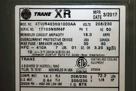
An image of the model and serial number. also available in the sub-cooling temperature with 10 degrees plus or minus 3 degrees.
Example image: 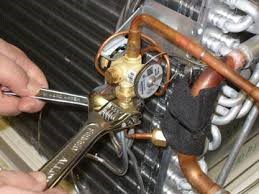
TXV being removed from an evaporator coil with two adjustable wrenches.
The TXV has become the most common metering device use in residential HVAC equipment for the mere purpose of increasing the efficiency of a heat pump or straight cool system. therefore any contractor or technician must familiarize themselves with this mechanical component. How to check the superheat and or adjust if needed, to replace it using the proper technique and procedures. to be able to recognize if the system is a fixed bore orifice instead of a TXV.To determine whether or not to charge in superheat or sub-cool depending on the metering device. We all know a piston you should charge a system using the superheat method and a TXV use the sub-cooling method. And verify that the superheat is correct if we charge in the sub-cool method because the TXV should maintain a proper superheat if the TXV is working properly allowing the needed amount of refrigerant in the evaporator coil base off the spring pressure and sensing bulb pipe temperature.